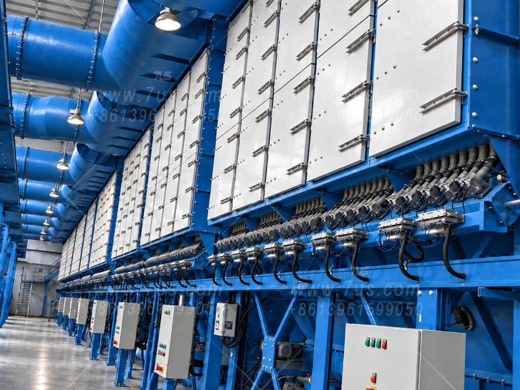
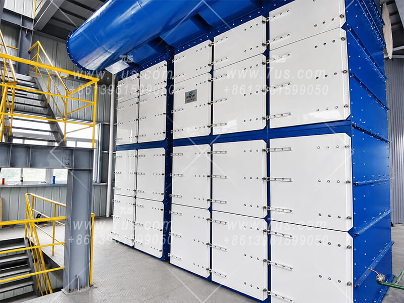
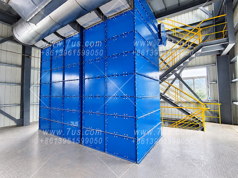
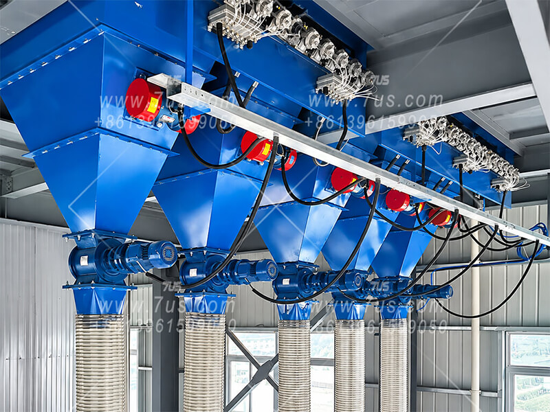
Compact side-insertion flat-bag filtration with pulse-jet cleaning and flexible modular construction for medium- to large-airflow industrial dust collection systems.
Side-insertion flat bag design for convenient front-side maintenance
10-slot standard for most applications; 8-slot and custom configurations available
Standard 1.5 m / 2.0 m flat bags, with custom lengths available
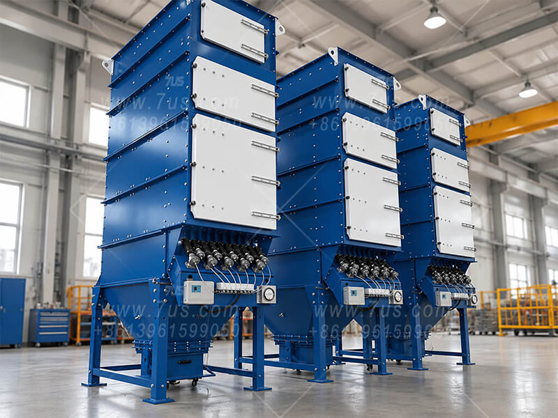
Flexible multi-layer and multi-module configurations for different airflow and site-space requirements
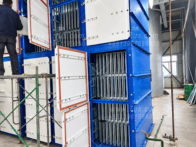
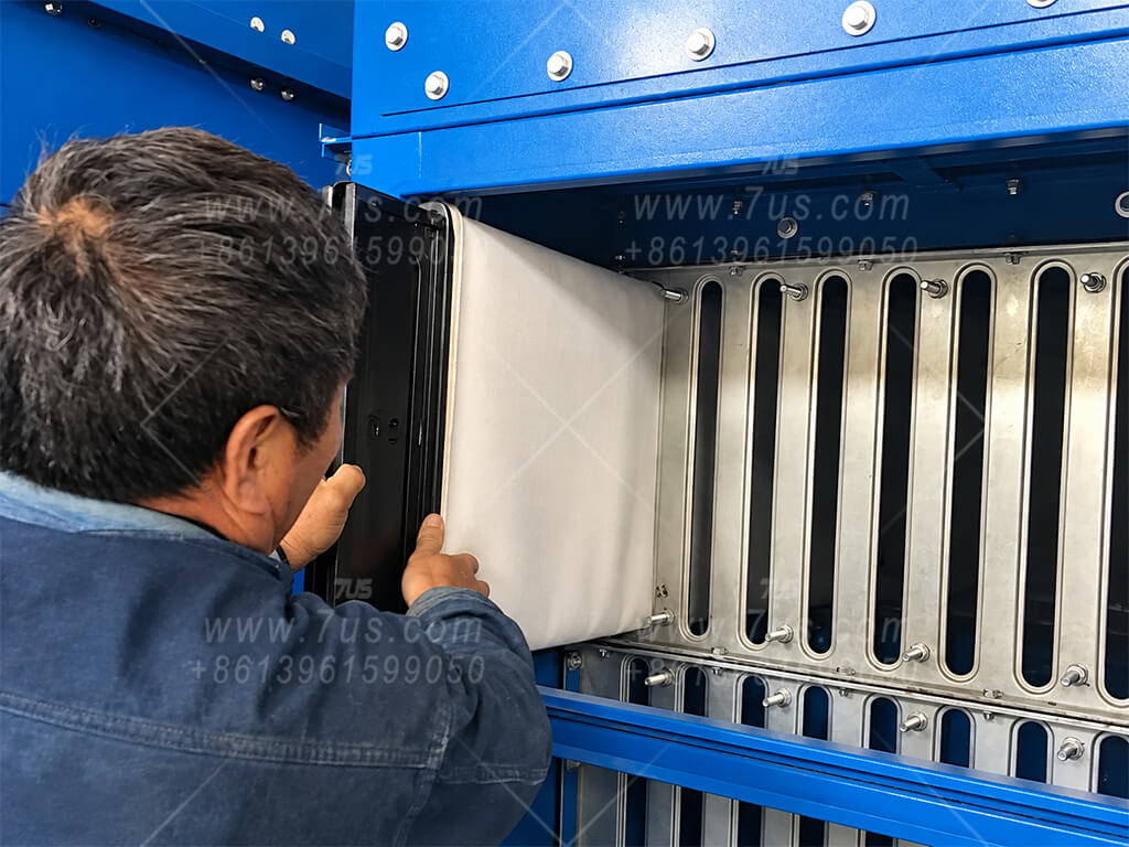
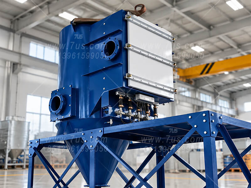
EHFBC uses flat envelope-shaped filter bags supported by rigid flat cages and arranged in compact vertical rows. The filter assemblies are serviced from the access side, creating a different maintenance layout from conventional top-entry round-bag collectors.
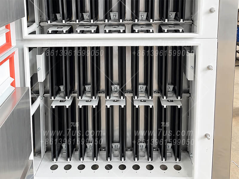
Open-door module view. Multiple layers of flat-bag cage assemblies are arranged directly behind the side access doors, making the internal layout easy to inspect and service.
01 · Structure
Compact Flat-Bag Array
Flat filter elements are positioned closely in parallel rows, allowing substantial filtration area to be packaged inside a relatively compact cabinet.
02 · Maintenance
Side-Insertion Service
Filter bags and cages are installed and removed from the service side, so routine replacement does not require overhead bag-pull clearance.
03 · Modular Layout
Multi-Layer Configuration
Rows, layers and module quantity can be combined around the required filtration area, airflow duty and available installation space.
Core concept: the flat bag, rigid cage, slotted mounting plate and side access door work as one serviceable filter module. Detailed bag, cage and mounting-plate construction is shown in the following chapters.
02How It Works
Airflow, Filtration & Pulse-Jet Cleaning
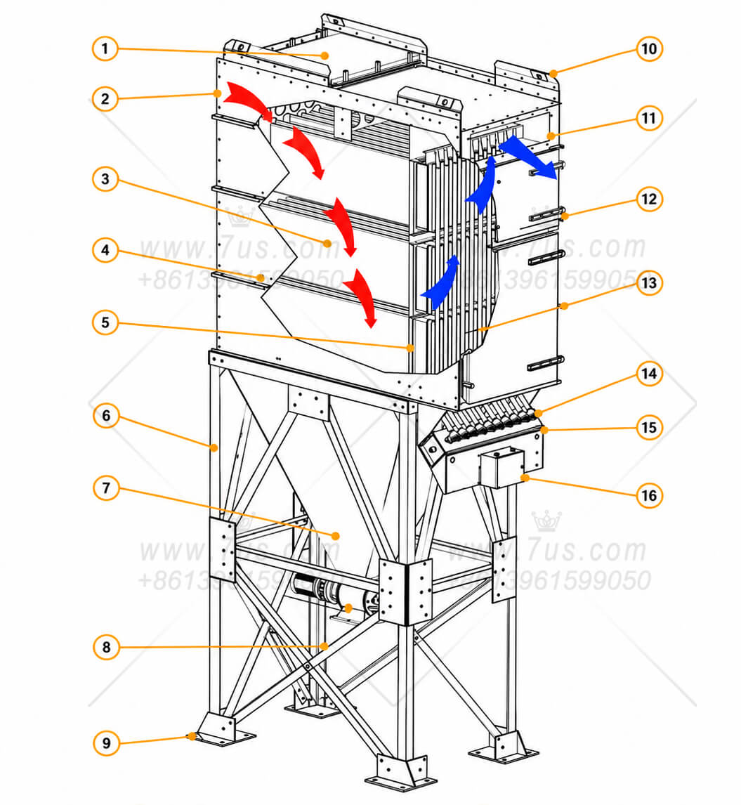
Dust-laden air enters the collector and moves through the flat-bag filtration zone. Dust is retained on the filter surface, while cleaned air passes to the clean-air side and exits the collector. Periodic pulse-jet cleaning releases accumulated dust toward the hopper.
01 · Dust-Laden Air
Air Enters the Filtration Zone
Dust-laden air enters through the inlet and is distributed through the collector body toward the flat-bag array.
02 · Filtration
Dust Is Captured on the Flat Bags
Dust is retained on the filter surface while the cleaned air passes through the filter media to the clean-air side and then leaves through the outlet.
03 · Pulse Cleaning
Compressed Air Releases the Dust Cake
The pulse system periodically cleans the filter bags. Released dust falls into the hopper and is discharged through the lower dust-removal device.
Component Legend
1Top Access Hatch
2Dust-Laden Air Inlet
3Flat Bags & Support Cages
4Collector Panel
5Tube Sheet
6Support Frame
7Hopper
8Discharge Valve
9Base Plate
10Lifting Lug
11Clean-Air Outlet
12Access Door
13Pulse Blow Pipe
14Pulse Valve
15Compressed-Air Manifold
16Pulse Controller
Airflow principle: red arrows indicate the dust-laden air path and blue arrows indicate the cleaned-air path. The diagram also identifies the principal service, pulse-cleaning and dust-discharge components.
03Flat Bag Installation & Retention
How the Bag-and-Cage Assembly Is Positioned and Secured
The flat filter bag, rigid support cage, slotted mounting plate and retaining clips work together as one side-service filter assembly. The details below show the component relationship, side insertion and the mechanical retention used after installation.
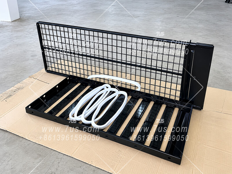
01 · BAG & CAGE STRUCTURE
Rigid Support for the Flat Filter Bag
The flat bag fits over a rigid cage that supports the filter media and maintains the required flat profile. The white sample shown here is the bag cuff, illustrating how the filter bag interfaces with the cage at the access end.
02 · SIDE INSERTION
Bag and Cage Enter as One Assembly
After the filter bag is fitted over the cage, the complete assembly is inserted horizontally from the service side. The bag seats into the corresponding slot in the mounting plate while the cage remains accessible from the front.
03 · RETAINING DETAIL
Shared Clips Secure Adjacent Cages
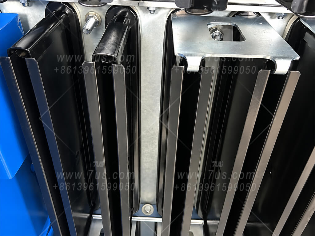
A retaining clip bridges the adjacent edges of two support cages. Upper and lower retaining points hold the installed cage assemblies in position after insertion.
04 · INSTALLED ARRAY
Compact, Repeatable Filter Arrangement
Once installed and retained, the flat bag-and-cage assemblies form an orderly side-service filter array. This view shows a typical 10-slot arrangement with consistent spacing and repeatable positioning across the filter row.
Service principle: the filter bag is supported by the rigid cage, seated in the slotted mounting plate and mechanically retained from the service side. Routine filter replacement therefore does not require overhead bag-pull clearance.
04Selection Logic
Dust First. Filter Area Second. Module Layout Last.
A required airflow alone is not enough to select a flat baghouse. The dust characteristics, concentration and operating conditions determine the filter media and design filtration velocity. That velocity determines the effective filter area, and only then should the required area be assembled from standard EHFBC modules to fit the available height, width and depth.
01Define Dust & ProcessDust type, particle behavior, concentration, temperature and operating conditions.
02Select Media & VelocityChoose filter media and a project-specific design filtration velocity.
03Calculate Filter AreaConvert the required airflow into effective filtration area.
04Choose Base ModuleSelect bag length and layer count around the site envelope.
05Combine ModulesAdd module columns until the required total area is achieved.
01 · DESIGN FILTRATION VELOCITY
The Same Airflow Can Require Very Different Filter Areas
Filtration velocity is selected from the actual dust and duty. The values below are typical preliminary design references, not universal ratings.
ULTRAFINE / VERY LIGHT DUST≈ 0.8 m/minTypical starting point for very fine, lightweight powders such as protein powder.
GENERAL DUST≈ 1.2 m/minTypical starting point for ordinary-concentration industrial dust.
WOOD DUST≈ 1.7 m/minTypical starting point for woodworking applications with suitable dust characteristics.
Engineering balance: a lower filtration velocity generally reduces loading on each square metre of filter area, but it also requires more filter area, a larger collector and higher capital cost. Final selection balances dust behavior, filtration performance, site space and total system cost.
02 · FILTER AREA CALCULATION
Calculate the Required Effective Area Before Choosing a Model
A = Q ÷ (v × 60)A = required effective filter area (m²) · Q = airflow (m³/h) · v = selected design filtration velocity (m/min)
This is why a request for “a 10,000 m³/h baghouse” is not enough by itself to select the equipment.
Same 10,000 m³/h airflow — three different design velocities
0.8 m/min≈ 208 m²Very fine / lightweight powder example.
1.2 m/min≈ 139 m²General dust example.
1.7 m/min≈ 98 m²Wood-dust example.
03 · STANDARD BUILDING BLOCKS
Standard Single-Module Models
Choose the required layer count from the tables below, then combine base modules to provide the total filter area required by the application. These are single-column modules, not fixed-airflow ratings.
EHFBC C / L / 15(20)
C = module columns · L = filter layers · 15 / 20 = nominal 1.5 m / 2.0 m bag length. With a standard 10-bag row, each 1.5 m column-layer provides about 15 m² and each 2.0 m column-layer about 20 m² of effective filter area.
1.5 m Bag-Length Modules
Common configurations · 2–8 layers
1500 mm
1.5 metre bag-length single-module models, with 10 bags per layer. Filter areas are approximate.
No.
Model
Layers
Bags
Filter Area(m²)
1
EHFBC1/2/15
2
20
30
2
EHFBC1/3/15
3
30
45
3
EHFBC1/4/15
4
40
60
4
EHFBC1/5/15
5
50
75
5
EHFBC1/6/15
6
60
90
6
EHFBC1/7/15
7
70
105
7
EHFBC1/8/15
8
80
120
10 bags per layer × approx. 1.5 m² per bag.
2.0 m Bag-Length Modules
Available configurations · 1–8 layers
2000 mm
2.0 metre bag-length single-module models, with 10 bags per layer. Filter areas are approximate.
No.
Model
Layers
Bags
Filter Area(m²)
1
EHFBC1/1/20
1
10
20
2
EHFBC1/2/20
2
20
40
3
EHFBC1/3/20
3
30
60
4
EHFBC1/4/20
4
40
80
5
EHFBC1/5/20
5
50
100
6
EHFBC1/6/20
6
60
120
7
EHFBC1/7/20
7
70
140
8
EHFBC1/8/20
8
80
160
10 bags per layer × approx. 2.0 m² per bag.
Base modules, not every combined model. Multiple base modules form one larger collector. Other slot counts and custom bag lengths are available to suit the project.
Combined-model example:8 × EHFBC1/6/20 = EHFBC8/6/20480 bags · approx. 960 m² total filter area.
QUICK AIRFLOW SELECTION · REFERENCE EXAMPLE
Start with Airflow — Then Confirm the Final Design
For customers who only know the required airflow, this compact table provides a fast preliminary reference based on a common 7-layer, 1.5 m bag module. Find the required airflow first, then contact 7US for project-specific engineering.
Modules
Reference Model
Filter Bags
Filter Area (m²)
Reference Airflow (m³/h)
Modules
Reference Model
Filter Bags
Filter Area (m²)
Reference Airflow (m³/h)
1
EHFBC1/7/15
70
105
10,000
6
EHFBC6/7/15
420
630
60,000
2
EHFBC2/7/15
140
210
20,000
7
EHFBC7/7/15
490
735
70,000
3
EHFBC3/7/15
210
315
30,000
8
EHFBC8/7/15
560
840
80,000
4
EHFBC4/7/15
280
420
40,000
9
EHFBC9/7/15
630
945
90,000
5
EHFBC5/7/15
350
525
50,000
10
EHFBC10/7/15
700
1,050
100,000
Reference basis1 module = EHFBC1/7/15 = 7 layers × 10 bags/layer = 70 bags · approx. 105 m² effective filter area. At approximately 1.58 m/min design filtration velocity, one module corresponds to a nominal reference airflow of about 10,000 m³/h.
Preliminary reference only: final model selection is not determined by airflow alone. Dust characteristics, concentration, operating conditions, filter media and the project-specific design filtration velocity must be confirmed before the final filtration area and module arrangement are selected.
04 · FIT THE AREA TO THE SITE
The Required Area Can Be Arranged in Different Heights, Widths and Depths
Once the effective area is known, choose the geometry around the actual installation envelope. The same total filter area can be arranged as a taller single module or as several lower modules placed side by side.
HEIGHT LIMITEDFewer layers, more module columns
Reduce vertical levels and add horizontal modules while preserving the required total filter area.
DEPTH LIMITEDUse shorter bags
Use 1.5 m or a custom shorter bag, then recover the required area through layers or additional module columns.
WIDTH AVAILABLEExpand horizontally
Add standard module columns in parallel without increasing the number of vertical layers.
CUSTOM GEOMETRYAdjust the building block
10-slot rows and 1.5 / 2.0 m bags are mainstream formats, not hard design limits.
Same filter area, different physical layoutsAbstract example using 1.5 m bags: both layouts provide about 120 m² of effective filter area.
1 × EHFBC1/8/15One taller module · ≈120 m²
=
2 × EHFBC1/4/15Two lower modules · ≈120 m² total
Cost-layout principle: where installation space is not constrained, fewer larger modules are generally more economical than splitting the same filter area into more smaller modules. Multiple modules duplicate items such as hoppers, discharge devices, pulse-cleaning hardware, cabinet / connection structures and site assembly work. When height, width, depth, transport or lifting conditions are constrained, the layout is adjusted to suit the project.
ILLUSTRATIVE 10,000 m³/h GENERAL-DUST DUTYAt 1.2 m/min → about 139 m² requiredThe target area can be met by more than one physical arrangement. The final choice depends on the available height, depth, width and preferred maintenance layout.
BUILD THE AREA, NOT A FIXED AIRFLOW MODELChoose the module geometry only after the required filter area is known.Use the fewest practical modules when space allows; split the area into more modules only when the installation envelope or logistics require it.
Selection principle: do not assign one fixed airflow rating to an EHFBC model. Confirm the dust, process conditions, filter media and design filtration velocity first; calculate the required effective filter area; then choose the most practical bag length, layer count and number of module columns for the installation site.
Other Flat-Bag Configurations
The EHFBC modular flat baghouse is the main platform introduced on this page. 7US also provides other flat-bag configurations for compact installations, local dust collection, high-vacuum systems and low-emission applications.
EHFBV Series
Insert-type flat-bag collectors designed for compact local dust control at material transfer points, silos and conveying systems.
EHFBI Compact Integrated Flat-Bag Dust Collector
Compact integrated flat-bag units for small and medium airflow applications, available as standalone equipment or for installation inside a containerized system.
High-Vacuum Flat-Bag Unit
High-vacuum flat-bag collectors for centralized vacuum cleaning and high-pressure dust extraction systems.
EHFBC-H Series
Flat-bag filtration combined with HEPA secondary filtration for low-emission applications and air recirculation.
05Factory to Site Installation
From Flat Baghouse Manufacturing to Project Completion
The complete manufacturing and installation process demonstrates how modular flat baghouse systems are transformed from individual components into a fully integrated dust collection solution.
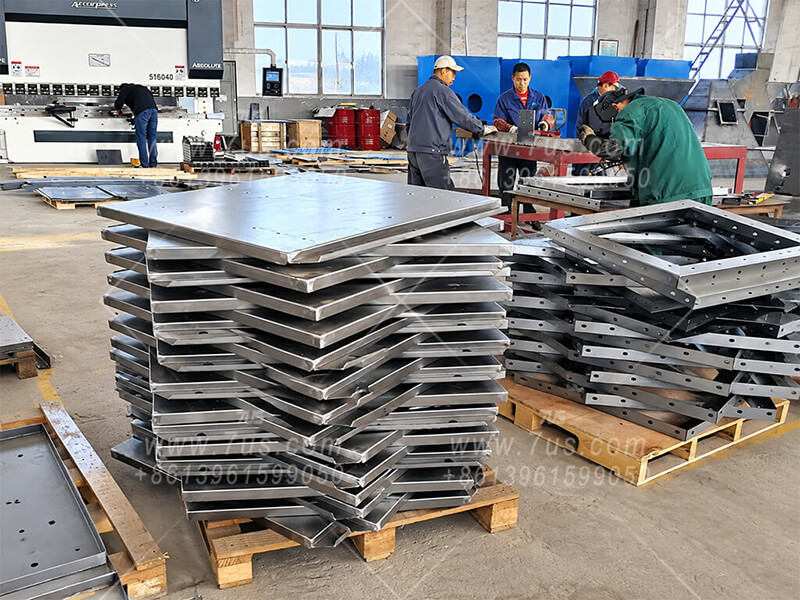
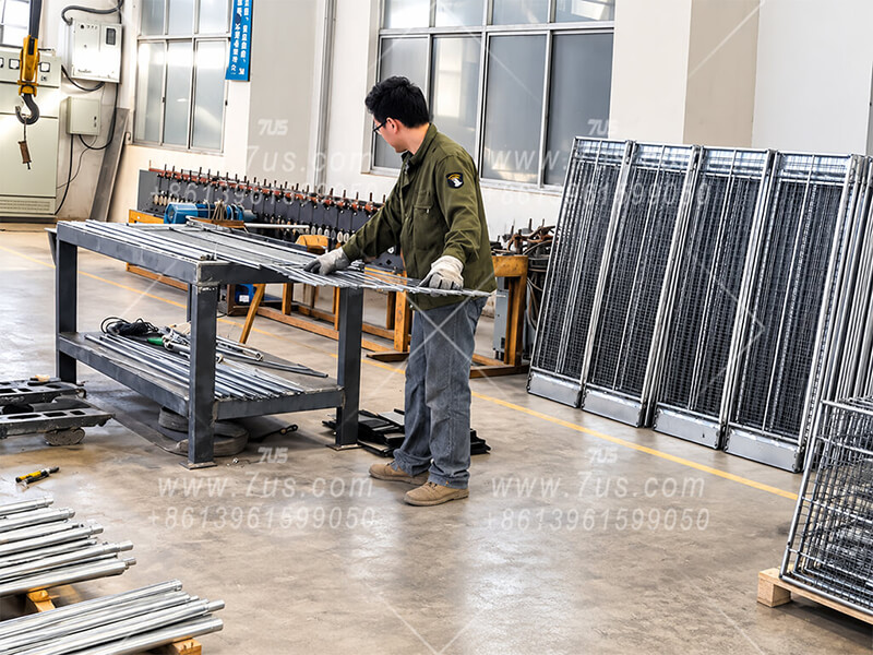
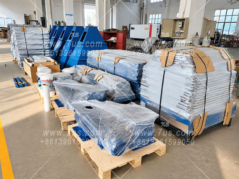
Sheet Metal FabricationPrecision-cut and formed steel components prepared for modular flat baghouse construction.
Flat Bag Cage ManufacturingIn-house flat bag cage manufacturing allows customized cage lengths according to project requirements.
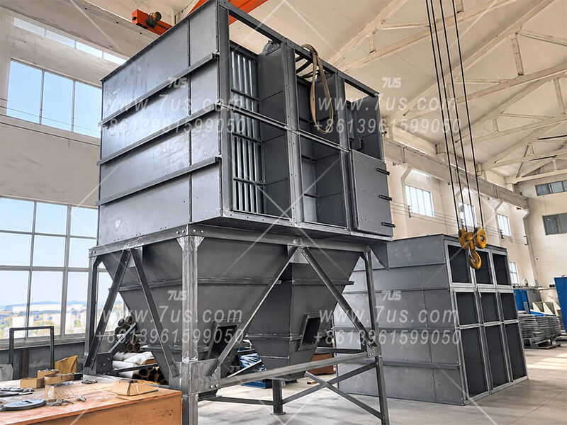
Trial Assembly Before Surface FinishingComplete module trial assembly before final surface treatment and coating.
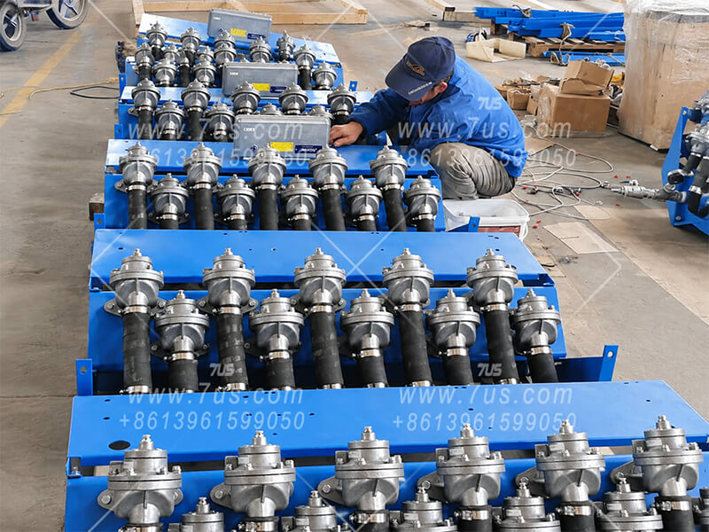
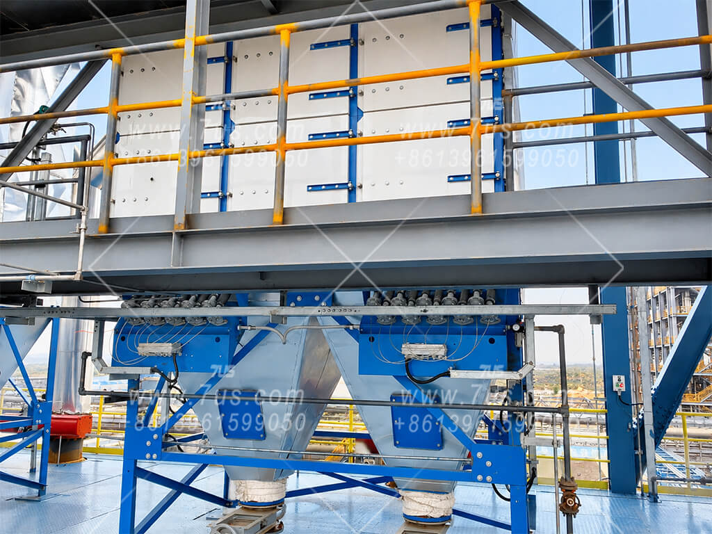
Pulse Cleaning System InstallationPulse valves, blow pipes and compressed-air cleaning components are installed as part of the complete cleaning system assembly.
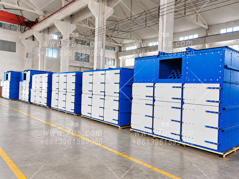
Final Assembly After Surface FinishingAfter surface finishing, the modules are finally assembled and inspected to ensure dimensional accuracy and overall quality.
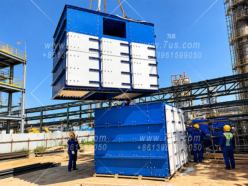
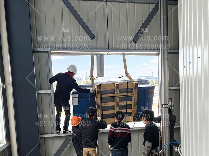
Site Lifting & InstallationModular sections lifted and positioned at the project site.
Site Installation & System IntegrationCollector modules integrated with the customer's process structure and duct system.
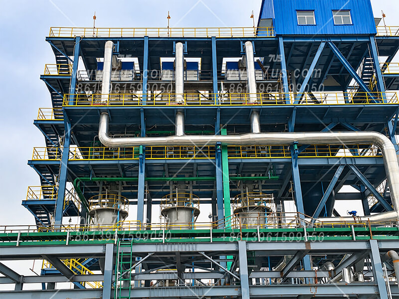
Completed Project InstallationCompleted dust collection system installed and ready for operation.
Send Us Your Dust Collection Duty
Provide airflow, dust type, temperature, concentration, installation space and power supply. We can then confirm the filter media, filtration area and EHFBC module arrangement.
From Individual Components to a Complete Flat Baghouse
When complete collectors or standard modules cannot enter an existing building, 7US can separate the equipment into individual components and rebuild the complete dust collector inside the factory.
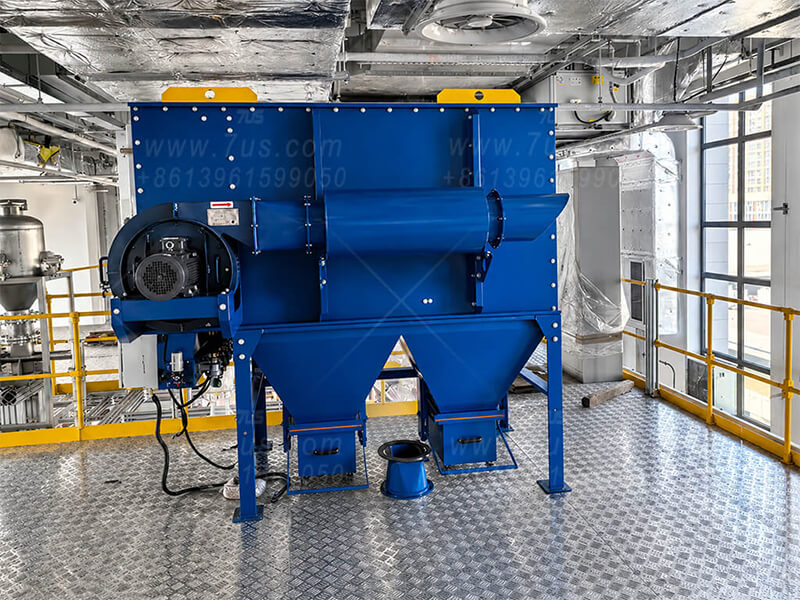
Marine Protein Powder Production Project: A production facility in Zhoushan, Zhejiang required a new dust collection system during a process upgrade. The existing multi-floor factory had operated for years, and major structural modification was not allowed. Because conventional complete units or standard modules could not pass through the available access routes, the flat baghouse was separated into individual components, moved through existing openings, and assembled inside the building.
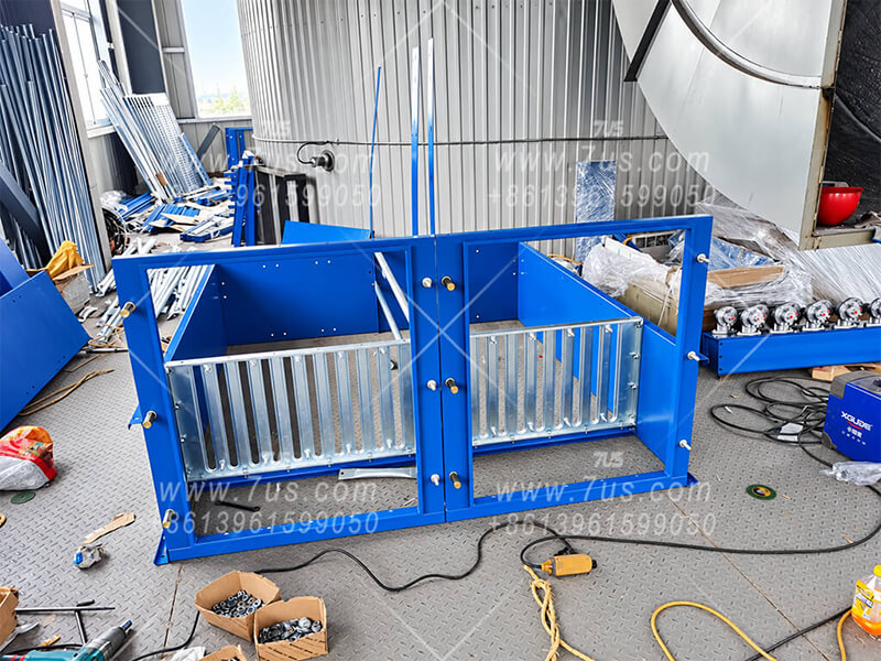
01 · Components PreparedThe flat baghouse is separated into individual components before delivery for restricted-access installation projects.
02 · Component Entry Through Existing OpeningIndividual components are moved through existing openings without changing the original building structure.
03 · On-Site Component AssemblySeparated components are assembled step by step inside the factory to rebuild the complete collector.
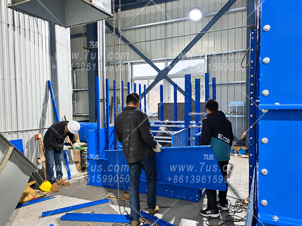
04 · Structural Assembly in Restricted SpaceThe collector structure is reconstructed according to the available installation area.
05 · Multi-Level AssemblyDifferent sections can be installed on different levels when floor height is limited.
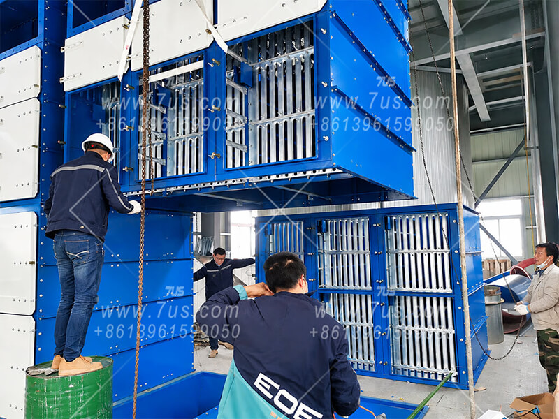
06 · Upper Housing InstallationThe upper housing is assembled inside the existing production building.
07 · Upper Housing IntegrationLarge collector sections are connected after entering through restricted access routes.
08 · Lower Housing & Final ConnectionThe complete dust collection system is finished without major building reconstruction.
07Applications
Industrial Dust Collection Applications
Flat baghouse dust collectors are widely used for industrial processes requiring stable filtration, flexible layouts and convenient maintenance. The following industries represent typical application areas for fabric filtration systems.
01 · INDUSTRY
Mining & Mineral Processing
Dust collection for crushing, screening, conveying and mineral processing operations with high dust loading.
Mining Dust Collector · Mineral Processing Dust Collection
02 · INDUSTRY
Cement & Building Materials
Large-volume dust control for cement production, raw material handling and building material processing.
Cement Dust Collector · Baghouse Filter
03 · INDUSTRY
Wood Processing
Used for centralized dust extraction in cutting, sanding, grinding and woodworking production lines.
Wood Dust Collector · Woodworking Dust Collection
04 · INDUSTRY
Metal Processing & Foundry
Applied for metal dust, grinding dust, casting particles and other industrial particulate collection.
Foundry Dust Collector · Metal Dust Collection
05 · INDUSTRY
Chemical & Powder Processing
Flexible filtration solutions for powder handling and chemical production environments.
Powder Dust Collector · Industrial Filtration
06 · INDUSTRY
Food & Protein Powder
Used for lightweight and fine powders requiring stable filtration and convenient maintenance.
Food Dust Collector · Protein Powder Collection
07 · INDUSTRY
Tobacco Processing
Used for continuous dust extraction in tobacco processing and production lines.
Tobacco Dust Collector · Tobacco Dust Extraction
08 · INDUSTRY
Battery Materials & Fine Powders
Suitable for fine powder processes requiring controlled dust collection and customized filtration.
Battery Material Dust Collection
08System Options
Configured for Your Process
Filter media and system components are selected around the dust, operating conditions and required discharge arrangement. The options below can be specified individually after the application requirements are reviewed.
01 · Filter media
Filter Bags & Media
Match the flat filter bag to the dust and operating temperature. Common bag lengths are 1.5 m and 2.0 m; other lengths and matching flat cages can be made to suit the project.
Polyester needle felt and membrane-laminated media
Antistatic and flame-retardant options
PPS, Nomex / aramid for suitable higher-temperature duties
Custom bag and cage lengths for site constraints
02 · Safety components
Explosion Protection
Where a combustible-dust assessment requires it, protection components can be incorporated into the project design.
Explosion vent panel or flameless venting
Grounding and compatible antistatic media
Component selection subject to project assessment
03 · Monitoring
Differential Pressure
Track filter resistance and cleaning performance with a differential pressure gauge or sensor.
Local reading or electrical signal
Alarm and control integration when specified
04 · Airflow
Fan, Motor & VFD
Fan and motor are selected for the required airflow, total system resistance and destination power supply.
Customer-specified international fan and motor brands
Optional VFD and fan silencer; VFD brand can be specified
Voltage and 50 / 60 Hz frequency configured for the destination country
05 · Controls
Pulse & Electrical Controls
Pulse valves, the pulse controller and control cabinet components can be selected to meet project requirements.
Customer-specified international brands for pulse valves and pulse controller
Electrical component brands and optional touchscreen can be specified
Control voltage and frequency matched to the destination supply
06 · Dust removal
Dust Discharge
Select the hopper outlet and conveying method around dust characteristics, sealing needs and collection frequency.
Manual slide gate or manual butterfly valve
Motorized rotary airlock valve or double-flap discharge valve
Motorized screw conveyor for multi-module collection
07 · Secondary filtration
HEPA Filtration
A downstream HEPA stage can be evaluated where the project calls for further particulate filtration. Final performance depends on the complete system design and selected filter grade.
08 · Additional treatment
Activated Carbon
An activated carbon stage can be considered for relevant odour or gas-treatment requirements after the dust is removed. Suitability depends on the actual contaminants and duty.
09 · Pre-separation
Cyclone Pre-separator
For heavy dust loading or larger particles, a cyclone can be evaluated upstream to reduce the load entering the flat baghouse.
Options are specified case by case. Explosion-protection components do not imply ATEX certification of the complete dust collection system.
09Project Inquiry
Planning a Flat Baghouse Project?
Share your dust conditions, installation constraints and supply requirements so we can review the filter area and module arrangement.
Operating Conditions
Please provide the dust type and concentration, required airflow, temperature and moisture, available height × width × depth, and the applicable emission requirements. Filter media and design filtration velocity are selected first; the required effective filter area and module arrangement follow.
Bag and Cage Lengths
Yes. The commonly used bag lengths are 1.5 m and 2.0 m. Other bag and matching cage lengths can be reviewed against the duty, cabinet arrangement and available space.
Restricted-Access Installation
Where whole sections cannot enter the building, a component-level delivery and on-site assembly plan can be evaluated. Please share door and window dimensions, lifting access and installation constraints so the scope can be confirmed.
OEM and Component Preferences
Yes. Colour, branding, nameplate arrangement and selected component brands can be specified for an OEM order. The exact configuration and supply scope are confirmed with the project.
Supply Scope
Yes. The collector body can be discussed separately or together with filter bags, fan and controls. We will define the interfaces and items included in the quotation.